
Никак не дождусь Портсигар из Поднебесной.
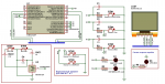
Пока симулировал проект в Протеусе.
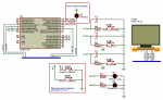
Пока симулировал проект в Протеусе.
Вложения
-
260.2 KB Просмотры: 1
Изменено:
/*
* https://github.com/cbm80amiga/HX1230_SPI
* https://github.com/cbm80amiga/HX1230_FB
* https://github.com/cbm80amiga/PropFonts
HX1230 96x68 LCD connections (header on bottom, from left):
#1 RST - any digital
#2 CE - any digital
#3 N/C
#4 DIN - D11/MOSI
#5 CLK - D13/SCK
#6 VCC - 3V3 or any digital
#7 BL - 3V3 or any digital - не подключен
#8 GND - GND
*/
#define LCD_RST 4
#define LCD_CS 3
#define LCD_VCC 8
#define LCD_DIN 11
#define LCD_CLK 13
#define DISP_SLEEP 30//время бездействия для откл дисплея
#define OPEN_COUNT 3//кол-во попыток откр коробки на 9 пине (PB1)
//#define PROTEUS_MODE 1//1-для эмуляции в протеус или закомментировать
#ifdef PROTEUS_MODE
#define VerProga "Proteus"
#else
#define VerProga "ver-1.03"
#endif
#include "HX1230_SPI.h"
HX1230_SPI lcd(LCD_RST, LCD_CS);
#include "term8x14_font.h"
#include "bold13x20digtop_font.h"
byte tcnt2;
byte open_box;
volatile long t,t1;
unsigned long time = 0; // 86390000;
volatile uint8_t time_sleep;
//время для отображения таймера
unsigned long sTime;
uint8_t hours1;
uint8_t minutes1;
uint8_t seconds1;
//время для установок таймера
long h1=23;
long m1=59;
long s1=0;
char buf[40];
int y=2;
int x=2;
String stringVar;
char charVar[9];
volatile boolean StartStopTimer = false;
volatile boolean sleep_mode = false;
volatile boolean open_mode = false;
volatile boolean low_bat = false;
volatile byte low = 1;
void setup() {
for (int i=2;i<20;i++){
pinMode(i, INPUT_PULLUP);
}
#ifdef PROTEUS_MODE
#else
PowerLow();
#endif
pinMode(LCD_VCC, OUTPUT);
digitalWrite(LCD_VCC, HIGH);
//Светодиод PD6 - при срабатывании прерывания по переполнению счетчика меняет свое состояние
//Светодиод PD5 - при наж люб кнопки и сраб прерывания PCINT1, меняет свое состояние
//Светодиод PD5 - выкл перед переходом в сон
PORTD &= ~((1 << 5) | (1 << 6));// Clear bit - low
DDRD |= (1 << 5) | (1 << 6);// Set bits - output
lcd.init();
lcd.clrScr();
lcd.setDigitMinWd(13);
#ifdef PROTEUS_MODE
lcd.setRotate(2);
#endif
setupInterrupt();
initButton();
sTime=3600*h1+60*m1+s1;
time_sleep=0;
open_box=OPEN_COUNT;
}
void loop() {
if (time_sleep>=DISP_SLEEP){
#ifdef PROTEUS_MODE
#else
lcd.sleep(true);
#endif
time_sleep=DISP_SLEEP;
}
if (time!=0){
t1=(long)(sTime-time);
if (t1<0){
PCMSK1 |= (1 << 0);//вкл кн 0
PORTD &= ~(1<<6);//выкл светодиод
lcd.sleep(false);
StartStopTimer = false;
TIMSK2 &= ~(1<<TOIE2);//Clear bit - disable the timer - pause
t1=0;
sleep_mode=1;
time=0;
open_mode = true;
open_box=OPEN_COUNT;
PORTB &= ~(1 << 1);// Clear bit - low - 9
DDRB |= (1 << 1);// Set bits - output
}
hours1 = (uint8_t)(t1 / 3600);
minutes1 = (uint8_t)((t1 / 60) % 60);
seconds1 = (uint8_t)(t1 % 60);
stringVar =String(hours1, DEC)+":"+String(minutes1, DEC)+":"+String(seconds1, DEC);
} else {
stringVar =String(h1, DEC)+":"+String(m1, DEC)+":0";
}
stringVar.toCharArray(charVar,sizeof(charVar));
snprintf(buf,sizeof(buf)-1,charVar);
lcd.setFont(Bold13x20);
lcd.printStr(x,y,buf);
lcd.setFont(Term8x14PL);
if (!StartStopTimer){lcd.printStr(0, 0, "pause");
if (time==0)lcd.printStr(0, 0, "pause , set");
}
if (low_bat){
lcd.printStr(25, 6, "LOW BAT");
} else {
if (open_mode){
lcd.printStr(25, 6, "OPEN");
} else {
lcd.printStr(25, 6, VerProga);
}
}
while(ASSR & 0x1F);
if (sleep_mode)sleepNow();
delay(250);
lcd.clrScr();
}
//упраление таймером Timer2
void setupInterrupt()
{
//Ожидание завершения стабилизации внешнего
//кварцевого генератора часов RTC:
for (uint8_t i=0; i < 0x40; i++)
{
for (int j=0; j < 0xFFFF; j++);
}
/*запрещаем прерывания */
cli();
/*Запрещаем прерывания Timer/Counter2 обнуляя OCIE2х и TOIE2.*/
TIMSK2 &= ~((1<<OCIE2A)|(1<<OCIE2B)|(1<<TOIE2));
/*Select clock source*/
ASSR |= (1<<AS2);
delay(300);
/*Configure timer2 in normal mode (pure counting, no PWM etc.)*/
TCCR2A &= ~((1<<WGM21) | (1<<WGM20));
TCCR2B &= ~(1<<WGM22);
/*Now configure the prescaler to CPU clock divided by 128*/
TCCR2B |= (1<<CS22) | (1<<CS20); // Set bits
TCCR2B &= ~(1<<CS21); // Clear bit
tcnt2 = 0;
/*Finally load end enable the timer*/
TCNT2 = tcnt2;
while(ASSR & 0x1F);
/*Обнуляем флаги прерываний Timer/Counter2.*/
TIFR2 |= ((1<<OCF2A)|(1<<OCF2B)|(1<<TOV2));
PORTD |= (1<<6);//заж светодиод
/* разрешаем прерывания */
sei();
}
/*
*Install the Interrupt Service Routine (ISR) for Timer2 overflow.
*This is normally done by writing the address of the ISR in the
*interrupt vector table but conveniently done by using ISR()*/
ISR(TIMER2_OVF_vect) {
//Как запустить неработающий часовой кварц (32768 Гц)
//http://www.getchip.net/posts/052-kak-zapustit-nerabotayushhijj-chasovojj-kvarc-32768-gc/
/*Reload the timer*/
TCNT2 = tcnt2;
//PORTD ^= (1 << 6);//инвентировать бит
time++;
if ((time % low)==0)PORTD ^= (1 << 6);//инвентировать бит
else PORTD &= ~(1 << 6);
time_sleep++;
sleep_mode=1;
}
//The External Interrupts are triggered by the INT0 and INT1 pins or any of the PCINT23...0 pins.
//The pin change interrupt PCI1 will trigger if any enabled PCINT[14:8] pin
//toggles.
//This implies that these interrupts can be used for
//waking the part also from sleep modes other than Idle mode.
void initButton() {
//pc0 pc1 pc2 кнопки pc3 - SUPERVISORY
PORTC |= (1 << 0) | (1 << 1 ) | (1 << 2 ) | (1 << 3 );// Set bits - pullup
DDRC &= ~((1 << 0) | (1 << 1) | (1 << 2) | (1 << 3));// Clear bit - input
//PCMSK1 – Pin Change Mask Register 1
//PCMSK1 Определяют условие генерации прерывания PCINT1. Если какойлибо
//бит установлен в 1, то изменение состояния соответствующего вывода
//вызовет генерацию прерывания
PCMSK1 |= (1 << 0) | (1 << 1) | (1 << 2) | (1 << 3);// Set bits
//PCICR – Pin Change Interrupt Control Register
//прерывание по изменению состояния вывода 0 или 1 или 2
PCICR |= (1 << PCIE1);// Set bits - When the PCIE1 bit is set (one) and the I-bit in the Status Register (SREG) is set (one), pin change interrupt 1 is enabled
}
//т.к. тактирование идет от кварца 32.768 кГц - событие должно иметь место вплоть до срабатывания прерывания
ISR(PCINT1_vect) {
if (!(PINC & 0x08))//срабатывает от SUPERVISORY при недостаточнлм питании
{
PCMSK1 &= ~ (1 << 3);//откл прерывание от SUPERVISORY
low_bat = true;
low = 5;
}
time_sleep=0;
lcd.sleep(false);
switch(PINC & 0x07){
case 6:{//наж кн 0
if (open_mode){
open_box--;
PORTB |= (1 << 1);//Set bits - high
break;}
if (!StartStopTimer) {
StartStopTimer = true;
TIMSK2 |= (1<<TOIE2);// Set bits - enable the timer - start
PCMSK1 &= ~ (1 << 0);//откл кн 0
} else {
StartStopTimer = false;
TIMSK2 &= ~(1<<TOIE2);//Clear bit - disable the timer - pause
}
break;}
case 1:{//наж одновременно две кн 1 и 2
if (!StartStopTimer){
h1=0;
m1=0;
s1=0;
time = 0;
}
break;}
case 5:{//наж кн 1
if (!StartStopTimer){
if (time == 0){
h1++;
if (h1>23){h1=0;}
s1=0;
sTime=3600*h1+60*m1+s1;
}
}
break;}
case 3:{//наж кн 2
if (!StartStopTimer){
if (time == 0){
m1++;
if (m1>59){m1=0;}
s1=0;
sTime=3600*h1+60*m1+s1;
}
}
break;}
case 7:{//при отпускании кнопки
if (open_mode) PORTB &= ~(1 << 1);// Clear bit - low
if (open_box==0) {
open_mode=false;
pinMode(9, INPUT_PULLUP);
}
break;}
}
PORTD ^= (1 << 5);//инвентировать бит
}
void PowerLow(){
//Для отключения периферии микроконтроллера существует регистр PRR:
/*Аналогоцифровой преобразователь
* Если функционирование АЦП разрешено, то он будет работать во всех
* «спящих» режимах. Соответственно, для снижения потребляемого тока
* модуль АЦП необходимо отключать перед переводом микроконтроллера в
* любой из энергосберегающих режимов.
*/
//Writing this bit to one enables the ADC. By writing it to zero, the ADC is turned off. Turning the ADC off while a
//conversion is in progress, will terminate this conversion.
ADCSRA &= ~(1<<ADEN);//Clear bit
//PRR |= (1 << PRTWI) | (1 << PRTIM0) | (1 << PRTIM1) | (1 << PRSPI) | (1 << PRUSART0) | (1 << PRADC)
PRR |= (1 << PRTWI) | (1 << PRTIM1) | (1 << PRUSART0) | (1 << PRADC);// Set bits
DIDR1 |= (1 << AIN1D) | (1 << AIN0D ); // Set bits - отключения входных цифровых буферов
//DIDR1 – Digital Input Disable Register 1
//When this bit is written logic one, the digital input buffer on the AIN1/0 pin is disabled. The corresponding PIN
//Register bit will always read as zero when this bit is set. When an analog signal is applied to the AIN1/0 pin and
//the digital input from this pin is not needed, this bit should be written logic one to reduce power consumption in
//the digital input buffer.
//Watchdog Timer Configuration
//WDTCSR – Watchdog Timer Control Register
MCUSR &= ~(1 << WDRF);// Clear bit
//WDE is overridden by WDRF in MCUSR. This means that WDE is always set when WDRF is set. To clear
//WDE, WDRF must be cleared first
WDTCSR &= ~((1 << WDE) | (1 << WDIE));// Clear bit - Watchdog Timer Stopped
//IVCE (Interrupt Vector Change Enable): бит разрешения изменения вектора прерывания. Данный бит должен быть установлен, чтобы разрешить изменение бита IVSEL.
//IVCE очищается аппаратно через четыре цикла после его установки или при установке бита IVSEL
MCUCR |= (1 << IVCE);
//IVSEL (Interrupt Vector Select): выбор вектора прерываний.
//Если установлен данный бит, то векторы прерываний перемещаются в начало загрузочного сектора флэш-памяти
// Установить бит разрешения изменения вектора прерывания (IVCE).
// В течение четырех машинных циклов внести изменение (записать 1 или 0) в IVSEL, при этом записывая лог.0 в IVCE.
MCUCR |= (1 << IVSEL);
}
void sleepNow(){
/*
* 4. Power-save (экономичный) - полностью повторяет Power-down,
* но в нем еще продолжает свою работу таймер/счетчик 2 в асинхронном режиме.
*/
//Power-save
SMCR &= ~(1 << SM2);// Clear bit
SMCR |= (1 << SM0) | (1 << SM1 ); // Set bits
PORTD &= ~(1<<5);//выкл светодиод
SMCR |= (1 << SE);// Set bits - sleep_enable
asm ("sleep");
SMCR &= ~(1 << SE);// Clear bit - sleep_disable
sleep_mode=0;
}